Between finishing my bachelor’s in mechanical engineering and starting my master’s in materials science, I decided to make a tensile testing machine.
If you have a similar plan, I hope sharing my process will provide you with some inspiration. A word of advice: if you can make a small footprint setup, a full-scale machine is pleasant to use, but also takes up a lot of space.
CAD design
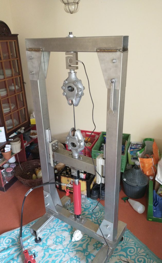
Initially, I intended to test aluminium and or bronze; therefore, I started with a sturdy frame and a hydraulic piston for loading. Admittedly, the DIY clamps are a bit flimsy compared to the frame and piston.
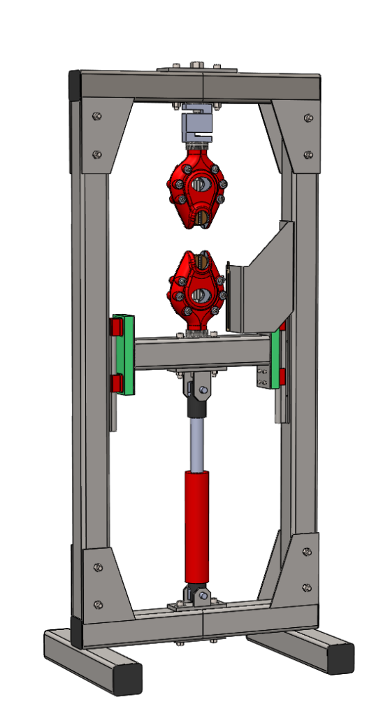
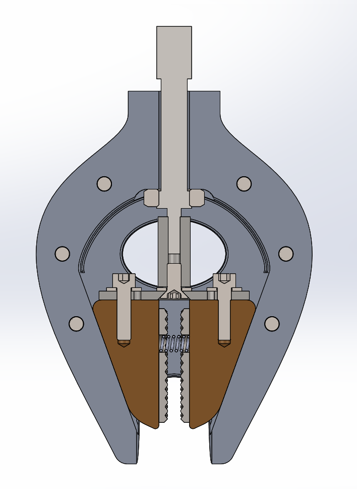
Left, CAD design of the frame. Right section view of the clamp showing the internal mechanism.
Constructing the frame was relatively straightforward. Drilling 13mm holes through stainless steel without a drill press wasn’t easy, so I decided to get the flat pieces shown in the photo lasercut at a local supplier.
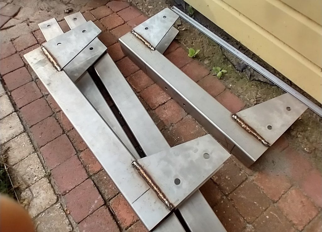
lasercut flat pieces welded onto the square tubes.
I wanted to make the clamps by casting. The design process for this took a bit more time and research into sandcasting, simulation, and molding.
Solidification simulation of one half of the clamp.
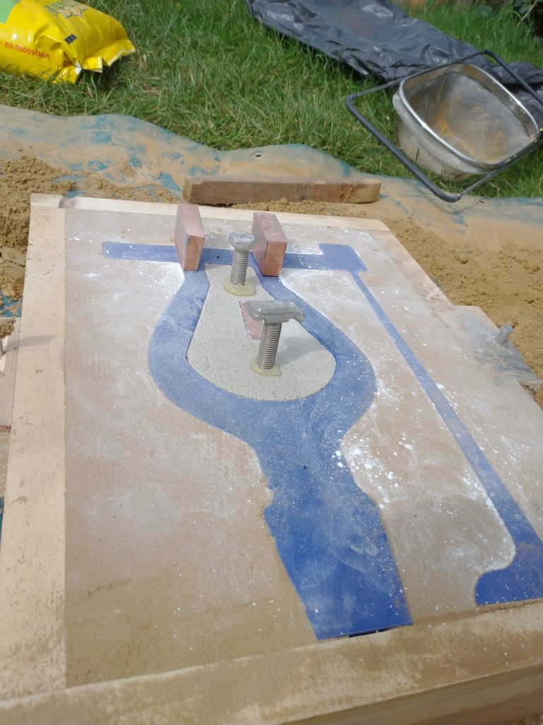
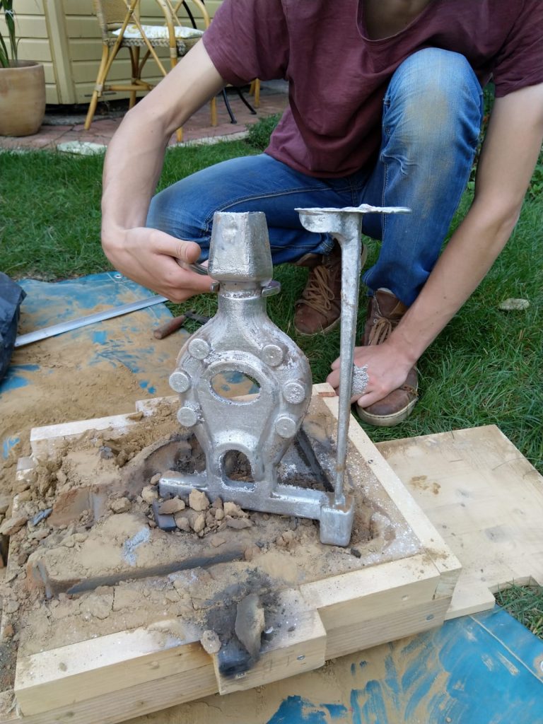
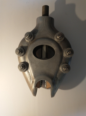
From left to right: Sand mold with plug, result directly after casting, result after post-processing.
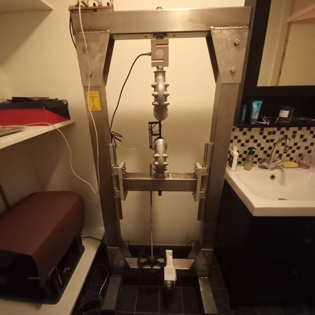
After finishing the tensile testing machine, I realised that I will primarily use it for 3D printed plastics instead of metals. Therefore, I replaced the hydraulic piston with a screw and a DC motor.
For other DIY tensile testing machines, I saw people using extensometer methods that I didn’t like. Such as: directly using the servomotor or stepper motor position (Difficult to separate the gauge length of the specimen from the clamping part of the specimen). Using digital calipers (heavy)or optical detection with a camera (best method, but requires more complex software or manual post-processing).
My solution was to use a high-resolution quadrature encoder. This solution is easy, cheap, and light. The only downside is that the resolution is limited.
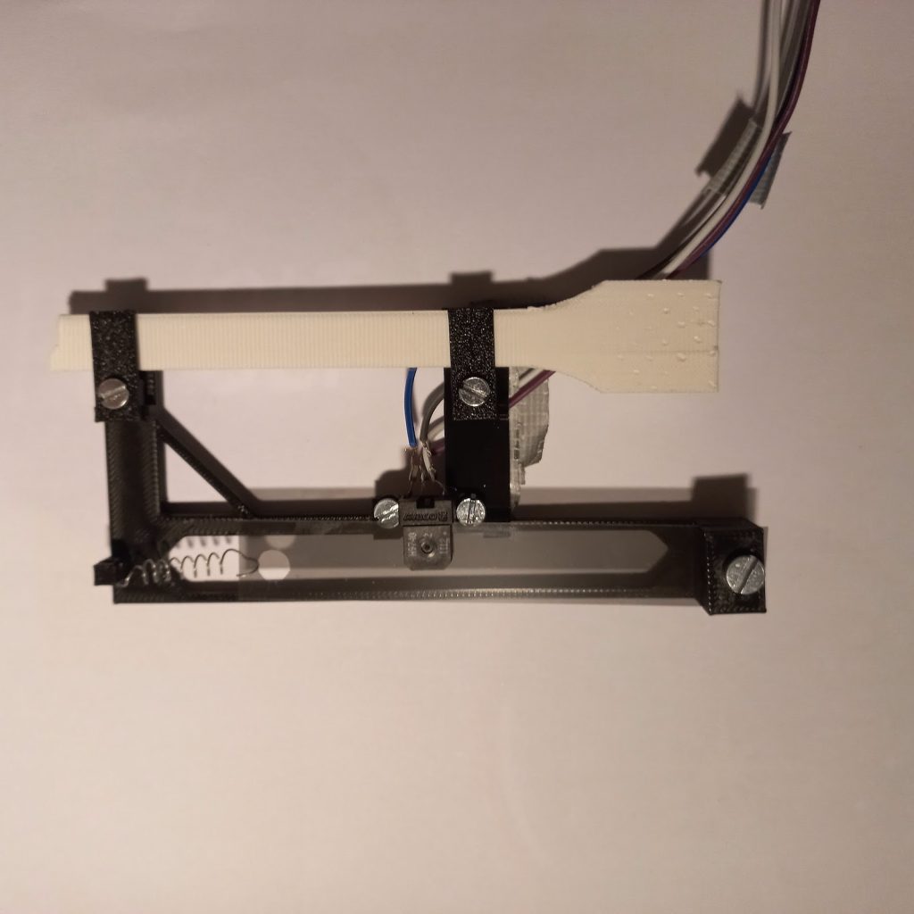
Extensometer with 300 lines per inch encoder. With a quadrature encoder this comes down to a 21 μm resolution.
If anyone wishes to copy this extensometer mechanism, please keep in mind that you need a high speed on your microcontroller. This makes it difficult to use the same microcontroller for the extensometer as the loadcell which benefits from averaging of readings to reduce noise. I solved this problem by using a separate microcontroller for the extensometer.
Initially, I used a cordless drill to drive the spindle. This works reasonably well, although the loading can be inconsistent. I am now using a fixed DC motor and benchtop power supply for slightly more consistent loading.
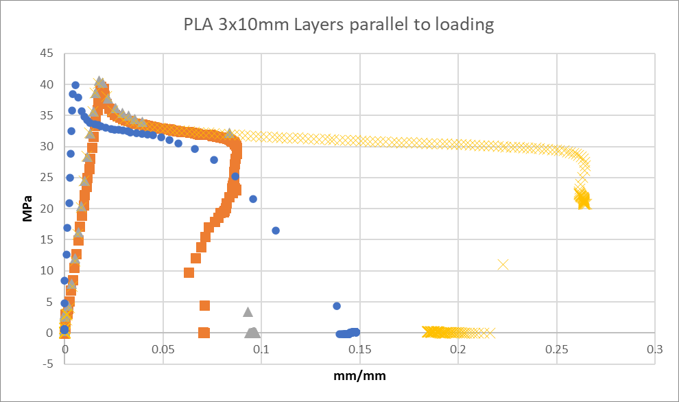
Differences in stress-strain diagrams due to variability in the quality of the 3D-printed material and inconsistent loading rate.